Advanced Turning Concepts
In order to take full advantage of the capabilities of SmartCAM Advanced Turning, there are several key concepts that must be understood and followed to successfully model your multifunction machining processes, and generate code. The following sections discuss and illustrate these concepts.
Default Coordinate Systems and Workplanes
Advanced Turning provides support for machines with main and sub-spindle configurations. Operations for each spindle are differentiated by defining toolpath on workplanes identified as main or sub-spindle planes. The default world workplanes (XY_PLANE, YZ_PLANE, XZ_PLANE, and ZX_PLANE) represent the main spindle coordinate system. The secondary SUB workplanes (SUB_XY, SUB_YZ, SUB_XZ, and SUB_ZX) represent the sub-spindle coordinate system. The sub-spindle coordinate system is a 180 degree rotation of the main spindle coordinate system around the world X axis. An Offset Sub-spindle option available under the Workplane menu can be used to shift the sub-spindle coordinate system along the world Z axis to a specified position. When creating new workplanes using the Define Planes dialog box, launched from Workplane Manager - New Plane, an On Sub-spindle option can be used to indicate the plane belongs to the sub-spindle. If the On Sub-spindle option is off, the plane is assumed to belong to the main spindle.
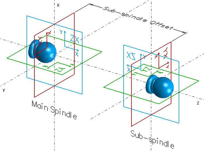
Sub-spindle coordinate system is a 180 degree rotation of the main spindle coordinate system about the world X axis
Turning Considerations
Turning Workplanes
Turning operations can be defined for either spindle by creating the toolpath while an appropriate main or sub-spindle plane is active. Turning processes for the main spindle should be defined on the ZX_PLANE or a main spindle plane coincident with and oriented similarly to the ZX_PLANE. Turning processes for the sub-spindle should be defined on the SUB_ZX plane or a sub spindle plane coincident with and oriented similarly to the SUB_ZX plane.
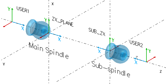
Default and User-defined, Main and Sub-spindle Turning Planes
Tool Orientations
Turning tools must be defined with respect to the machine Front view, regardless of whether they will be used on main or sub-spindle turning planes. When defining turning toolpath for the sub-spindle it is best to view the SUB_ZX plane from its positive Z looking toward the origin, since the path direction and offset side are defined with respect to this view orientation.
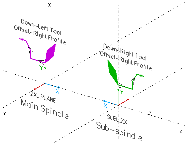
Offset Right Toolpath using Down-Left Turning Tool for Main Spindle and Down-Right for Sub-spindle
Milling Considerations
Face Workplanes
Milling processes on the main spindle part face should be defined on the XY_PLANE. Milling processes on the sub-spindle part face should be defined on the SUB_XY plane. The output method for toolpath defined on the system XY planes is determined by the code generator SMF question #443.
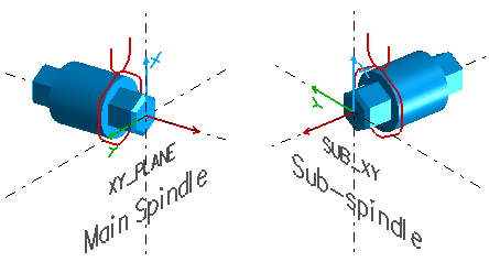
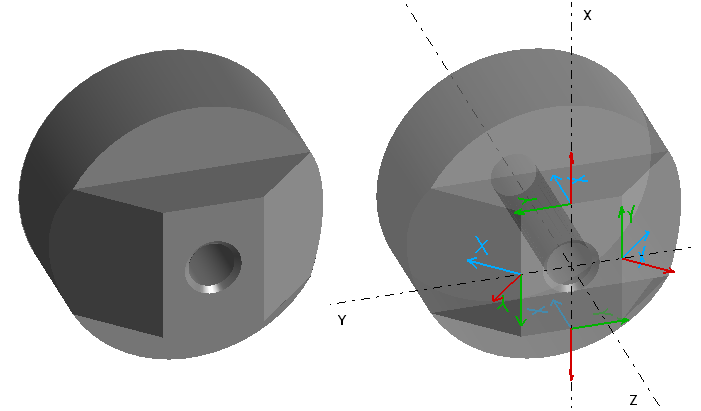
Face Hex Features Machined using Continuous Profile on XY Planes
C-axis Face Index Workplanes
For machines with Y axis, or the ability to command the C axis in terms of a Y axis movement, user-defined planes parallel and oriented similarly to the main spindle XY_PLANE or sub-spindle SUB_XY plane may be used to achieve an index and cut strategy for machining face features. User defined workplanes are defined for each feature at the respective rotation positions. The part is then indexed to bring each workplane into position, and the feature is cut using XY motion.
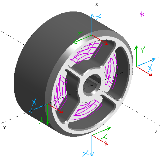
Repetitive Face Features Machined using User-defined C-axis Face Index Planes. Note: Workplanes displayed offset from world Z axis for illustration clarity.
Side and B-axis Index Workplanes
The B-axis support of Advanced Turning requires that side and inclined face milling operations be defined on user defined workplanes that are rotations of the main spindle XY_PLANE or sub-spindle SUB_XY planes around the world Y-axis.
B-axis Milling Workplanes
Coordinate Input
The World Coordinate input option in the Utility - Display Modes dialog box is not supported for planes other than the standard main spindle workplanes. When a sub-spindle or user defined workplane is active, local input should be used.
Code Generation
There is a relationship between how a toolpath is modeled and how the code generator must be configured. For machines that do not have a rotary B-axis, side milling can be performed directly on the main and sub-spindle YZ planes. However, the local axes must be mapped to the corresponding world axes for output in the code generator. Machines that have a rotary B-axis on the other hand, require side and inclined milling to be performed on user defined planes that are rotations of the XY plane about the Y axis. The code generator axis mappings from these local planes to the world are different, and require a sign reversal of one axis.
Code generators for machines with sub-spindle should be configured to Local output, and different machine coordinate system offsets should be output for each spindle. In order to get the correct axis output, the primary and secondary axes can be conditionally changed in the @PROLOGUE section using the #SMFCHANGE word.