Create and Machine Rest Mill Regions.
SmartCAM can identify machining areas (regions) that can not be cut by a particular tool due to its tool diameter being too large to fit a profile's geometry. By letting SmartCAM know the previous tool and tool that will be used for clean up, it can determine from a set of input profiles where these areas are, and then automatically create rest mill regions. These regions can be created in a container, and then recalled and reprocessed at a later time, if necessary. Rest Mill regions can be cut using a Region Rough process and the clean up tool.
Use the model below to try this exercise.
| Milling applications | restmill.pm5 |
|---|
Step One: Create Pocket Profile
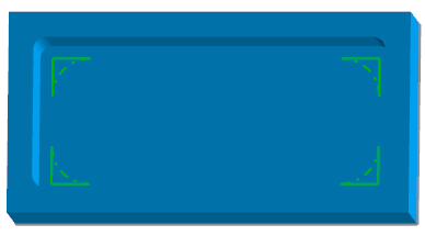
This model contains a rectangular pocket and two predefined steps. The first step uses a .50 diameter end mill for roughing the pocket. This tool will leave uncut areas in the four pocket corners. The second step uses a .125 diameter end mill, which will be used to clean up the left over material. This model also contains a hidden stock boundary and roughing pocket toolpath for use with Verification.
Region operates on 2D profile geometry, so it is necessary to first extract a profile of the pocket boundary.
- Start a SmartCAM milling product and open restmill.pm5.
- On the Insert Properties bar, change to CAD mode (Layer) and select Layer 2.
- Make sure the Workplane is set to the XY_PLANE, and set the Profile Top to .5 (the top of the pocket).
- Select Create - From Solid - Boundary, and set Create From to Surface, and select the Surface label and click the surface at the bottom of the pocket (element 16). Press Create.
Step Two: Create Rest Mill Regions
Since the solid part is no longer required for the other operations you can hide it to clear the graphics view.
- Put the new layer 2 profile in the active group.
- Select Create - Regions - Rest Mill Region, and set Region Type to Tool Center. This creates the region based on the material left from the previous step, and where the clean up steps tool center will be calculated.
- Set Previous Step to 1, Next Step to 2, and Profile Side to Right. Press Go.
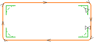
The four regions are created in a single container that can be recalled if modification is needed.
Step Three: Machine Rest Mill Regions
- On the Insert Properties bar, change to CAM mode (Step) and select Step 2, and set Clear to .6.
- Deselect the pocket profile and then place the Rest Mill regions in the active group.
- Select Process - Rough - Region Rough, and set Path Type to Part Offset, Width of Cut to .03, and Depth of Cut to .5. Press Go.
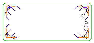
The toolpath is also created in a container that can be recalled and reprocessed later if changes are required. Experiment with different Path Types and settings to become familiar with the many ways regions can be machined.
Step Four: Verify Rest Mill Machining
- Open Planner - Job Info - Work Setup and enter
999for the Stock Layer. You can also open the Job Information window directly, using the Job Info toolbar button ( )
) - Open Utility - Options - Verification Options and set the following properties:
- Tool Display Style: Solid
- Draw Path: None
- Draw Rapids: No
- Draw Endpoints: No
You can access Verification Options directly, using the Options button on the Verification window. (
 )
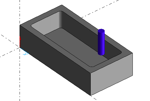
) - Select Process - Verification and click on the mode icon to enable Material Removal.
- Press the Play to run the simulation.
Done
This exercise is complete.