Integration with SmartCAM User Interface
There are several ways to integrate your custom macros or panels into SmartCAM. The macro or panel can be assigned to a hotkey, such as SHIFT+F7 or ALT+F4; it can be associated with an icon on the Toolbar; it can be added to a special User main menu selection; or it can be integrated into existing Create, Edit, or Process menus.
Hotkeys
Entries in the application .INI file associate a macro or panel with a hotkey. Complete the following to associate a macro, panel, or SWEL command with a hotkey.
- Open your application INI file in a text editor
Load your application's INI into a text editor, such as Notepad. Make sure your SmartCAM application is closed and not running.
If unsure where the application INI files reside, temporarily open your SmartCAM application. Select Help - About, the
Configuration Locationpath, at the bottom of the About box, is the location of the INI files. You can click the Open Folders button to launch Windows Explorer, which opens in the folder with the INI files.Close your SmartCAM application.
- Locate the [Hotkeys] INI section
The
[Hotkeys]section shows the various hotkey combinations supported by SmartCAM. Locate the key or key combination you want to assign to your macro or panel. - Make the assignment
Remove the leading semicolon if the key or key combination you want to use is commented out. This will uncomment the line. Now, tell SmartCAM what to assign to this hotkey.
Macro
To assign a macro, use the following syntax:macro "path\filename.ext"For example, to assign
C:\MACROS\ViewCustom.mcltoSHIFT+F10, the INI entry would look like:SHIFT+F10=macro "C:\MACROS\ViewCustom.mcl"Panel
To assign a custom panel, use the following syntax:
panel "Panel Name"For example, to assign the
Path Lengthcustom control panel toSHIFT+F10, the INI entry would look like:SHIFT+F10=panel "Path Length"SWEL Command
SWEL(SmartCAM Workspace Environment Language) commands give you access to most SmartCAM functionality, such as Views, Groups, dialogs, and panels. You can find a complete list of SWEL commands and symbol names in theswel_doc.htmfile located in the SmartCAM SHARED directory.For example, the Top view orientation is assigned to the F9 hotkey with:
F9=do "ViewTop" - Save the INI file
Save the application INI file. Launch your SmartCAM application and use the Hotkey to verify that it works.
Note: A Custom PCB Panel cannot be assigned to a Hotkey unless associated with a SmartCAM main menu entry. Assigning PCB panels to menus is discussed later.
It is not recommended that SmartCAM hotkeys be replaced with custom hotkeys.
Iconbar.Def
The ASCII text file, ICONBAR.DEF, is used to configure the panels, buttons, and icons that
can be added to your Toolbar. This is a SmartCAM maintained file, which includes the button definitions
for the functionality that ships with SmartCAM.
Do not make changes to this file. This file is overwritten during updates and new product installations.
However, the button definition code and formatting in the ICONBAR.DEF can be manually added to your personal custom Toolbar button configuration files. This allows you to add your custom panels and macros to your Toolbars. For most purposes, this is never required. You can use the Edit Toolbar functionality to add built-in or custom macro icons to your Toolbar.
The file is located in the SmartCAM SHARED\ICON directory. By default, this path would be in your versioned files folder:
SmartCAM\SmartCAMv#\Shared\Icon\
The format for an entry in this file is:
BUTTON "Display Name"
EVENT <command> <path or name>
ICON "<icon name>"
HELPLINE "Optional single line help text"
ICNTXTONE "Toolbar button text line one"
ICNTXTTWO "Toolbar button text line two"
The first line establishes this is a BUTTON definition. The "Display Name"
is the name associated with this functionality. This is the name displayed in the Predefined
Buttons list of the Edit Toolbar window.
Note: There is also a BTNBIN button type. This is a special type of toggle button. You can include Toolbar icons based on the BTNBIN events, but can not create your own. The BTNBIN buttons stay active until unselected or overridden, such as many of the buttons on the Group Toolbar.
The EVENT line specifies the action to be taken when BUTTON is triggered. The syntax
is the same as the syntax used to assign a macro or panel to a hotkey.
The ICON entry sets which icon is displayed when the macro or panel is associated with the
icon-based Toolbar, or when a custom PCB panel is displayed. The icon name is the filename for
the icon file, without the .ico extension.
SmartCAM will check two locations for your icon file. First, it will look in the SHARED\ICON
folder, which is the same folder that contains the ICONBAR.DEF file. If not found there, it
will check the folder where the associated macro resides. If found in neither location, a blank button
will be created. You should place your custom icon files in the same folders as their related macro files.
The HELPLINE is optional. When creating an entry for a custom PCB panel, this line is unnecessary, as the status bar help is stored with the panel. Adding a single-line help message is a good idea when working with a macro definition. The text entered here is displayed in the SmartCAM status bar or tooltip, depending upon how the SmartCAM application is configured.
The ICNTXTONE and ICNTXTTWO are used to enter two short lines of text. This text is displayed on the Toolbar when you configure your Toolbar to display button text.
As an example, the following is the Path Length custom PCB panel entry.
BUTTON "Path Length"
EVENT panel "Path Length"
ICON "PathLen"
HELPLINE "Find length of profile"
ICNTXTONE "Path"
ICNTXTTWO "Length"
This assumes an existing icon, with the filename PathLen.ico, is located in the same folder
as the macro called by the Path Length dialog.
Icon
SmartCAM uses the original Windows icon format (not XP or Vista), saved in a ICO format with an .ICO extension. The applications support up to 256 color icons. The icons must use the Windows BMP format for storing the image, PNG format images are not supported.
SmartCAM's Toolbar can be displayed in three sizes: Small, Medium, and Large. So three icons are needed for the various sizes; if a required size is missing, SmartCAM will attempt to rescale the existing icon image; however, the resize results are not optimal. The three sizes for icons needed are: 19x19, 24x24, and 32x32 pixels.
All three icon sizes are stored in a single ICO file.
Important Information
Since the ICONBAR.DEF is a free-format ASCII text file the SmartCAM installation routine cannot update the file. Instead, it overwrites it on each new installation or upgrade. This means any changes to the file will be lost after a re-installation.
However, if you make the same changes in your custom Toolbar button configuration file, you will not have to worry about the file being overwritten.
You do not need to edit the Toolbar button files directly. Instead of manually adding the button configurations, right-click on the Toolbar. Then select Edit Toolbar from the pop-up menu. From the Edit Toolbar window, you can add, remove, and reorder the buttons on the Toolbar chosen.
Toolbar
The SmartCAM Toolbar uses an ASCII text file to select what icons are displayed and in what order. The
file is saved with a .BGP19 extension and, by default, is kept in the same directory as the
ICONBAR.DEF file described above. When reviewing documentation, the terms "Toolbar"
and "Icon Bar" are the same; one is older terminology being phased out.
SmartCAM ships with several preconfigured Toolbar button files. You can modify the default shipping .BGP19 files, but like the ICONBAR.DEF files will be overwritten during new installations and updates. So, you will need to add your custom buttons back into the file after installing a new application version.
Two files control SmartCAM's Toolbars. There is a Button Group file
(*.BGP19). The Button Group file contains a list of the buttons to display on a single
Toolbar. When the Toolbar is visible, it will display the buttons configured in this file, in the order
they appear in the file.
Then there is a Toolbar Set or Toolbar Configuration file. This file contains a list of all imported Toolbars (imported .BGP19 button group files), whether the Toolbar is displayed or not, the Toolbar's location and size, the size of the buttons, whether buttons are aligned to the left, right or center (top, bottom, or middle) of strip, and whether button text is displayed and where the text is displayed. In effect, it contains the layout of the Toolbars.
The Toolbar Configuration files are named with a .BFG19 extension.
Since the ICONBAR.DEF, *.BFG19, and *.BGP19 files, which ship with SmartCAM, can be overwritten by subsequent updates. If you want to make changes to these files, you should create your own files and modify them. If your files are not named the same as the SmartCAM files and in the same locations, they will not be affected by later installations.
SmartCAM installations create a common area, a folder tree where you can make your versions of these files and keep them readily available and safe from updates. This path is:
\ProgramData\SmartCAM\Common\
It is recommended that you create an ICON\ subfolder, under ..\Common\, to use when creating your Toolbar configuration and button group files.
Creating Button Group Files
If you want to modify a shipped Button Group file, it is recommended that you make a copy of the file and make changes to it instead. To do that, complete the following:
- Start your SmartCAM application
- Right-click on the Toolbar you want to work on and select Copy Toolbar.... Enter the location (recommend the common\icon folder) and the filename to use. Click on the Save button.
- A copy of the Toolbar will be saved and loaded.
- The original Toolbar and the copy are loaded and displayed; you will want to remove the original
file. So, right-click on the original Toolbar and select Remove Toolbar.
If you are not sure which of the two Toolbars is the original. Right-click on one of them and select the Edit Toolbar menu option. A Toolbar File status line displays the name of the Button Group File. Since you provided (or accepted the default) name for your copy, you can use this to tell which Toolbar is which.
Now, any changes made to the Toolbar will be made to your copy.
Creating Toolbar Set Files
Like Toolbars, you can make and use a copy of the Toolbar Set file. Doing so it recommended to protect it from future updates.
- Start your SmartCAM application
- Either use the menu item Utility - Toolbar Sets - Copy... or right-click on the Main Menu bar and select Copy Toolbar Set... from the pop-up menu.
- Enter the name and location for the copy of the file. We recommend saving in the Common\Icon folder mentioned above.
- Click the Save button. The Set file will be saved, and your copy will become the new active configuration file. Any changes you make will be in your files, not the shipping files.
To ensure that any changes to the Toolbars are reflected, after a product update or new version installation, the installation updates the applications to use the default Toolbar Set file. After the update, your changed custom Toolbars may not be displayed. You can easily switch back to your custom Toolbar Set file and your custom Toolbars using either Utility - Toolbar Sets - Choose and selecting your custom Set file.
It is recommended to review the What's New help topic and check the displayed shipping default Toolbars to see what changes have been made for this release. Depending on the change, it may affect your custom Toolbar configurations.
Macros and PCB Panels
Your custom macros can be added directly to your custom Toolbar, using the functionality on the Edit Toolbar dialog.
Your custom CTK panels must be configured as Toolbar buttons before being used. See the topic about the
ICONBAR.DEF for information about how to create a BUTTON. This Button
definition would be added directly to your Toolbar button configuration file in the order you would
like the button to be presented.
Configure the Toolbar
How and where your Toolbar is displayed can be changed in several ways. Using Utility - Toolbar Sets - Configure opens the Configure Toolbar dialog box. You can right-click on the Main Menu bar and pick Configure from the pop-up menu.
The Configure Toolbar dialog box allows you to change the name of the Toolbar. This is not the filename. It is the displayed name that you right-click on the Main Menu to hide and show Toolbars.
You can also change the location where the Toolbar is docked, whether it is visible, and make it a floating Toolbar (a floating window, not docked to the edge of the graphics view).
Since you did not select a Toolbar before opening Configure Toolbar, you will need to use the Bar drop-down menu selector to pick the Toolbar to modify.
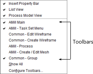
Right-clicking on the Main Menu bar opens a pop-up menu that contains a list of the Toolbars associated with the open Set file. Clicking on an item enables and disables visibility. Toolbars that are displayed have a checkmark next to them.
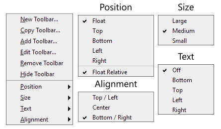
Right-clicking on an individual Toolbar brings up a pop-up menu that allows specific changes to the selected Toolbar. The Position pull-right menu lets you set which side of the graphics view to dock the Toolbar, or whether to make it a floating Toolbar. The Size menu selects which size to use for icons: small, medium, or large.
The Text menu turns on or off descriptive text for the Toolbar icons. If enabled, it also lets you select where to display the text: above, below, to the left, or the right of the icon. Finally, the Alignment menu lets you set the alignment for the icons. They can be justified to the Top/Left (Top for vertical, left for horizontal Toolbars), Bottom/Right, or centered in middle of Toolbar.
Displaying a new Toolbar File
You can display multiple Toolbars in SmartCAM. To display a new shipped Toolbar or a custom Toolbar that you have created and are maintaining, do the following:
- Right-click on an existing Toolbar and choose Add Toolbar... from the pop-up menu. Or use Utility - Toolbars - Add. This displays an Open dialog, with the default path being the location where the SmartCAM shipped Toolbar configuration files reside.
- Browse to and select the Toolbar button configuration file you want to use. Current Toolbar
button configuration files have a
.BGP19extension - which stands for "button group."You can also import older SmartCAM
.BARconfiguration files. When a .BAR file is opened, a new file with the new .BGP19 extension is created. This new file is created in the folder where the original .BAR file resides. It is the newer .BGP19 file that is actually displayed by SmartCAM.
Adding to the Toolbar
- Right-click on the Toolbar you want to modify, select Edit Toolbar from the pop-up menu.
- The
Predefined Buttonslist contains a sorted list of all the icons defined in theICONBAR.DEFfile. Select the icon to add. - In the
Active Buttonslist move the highlight bar to the location where you want to add the new icon. Then use the arrow button (<) to move the icon to your Toolbar. - You can use the
Move Up/Downbuttons to reposition the icon as needed. - Accept to add the icon to the bar.
Modifying Toolbar Icons
To change an existing Toolbar button, right-click on the Toolbar and from the pop-up menu select Edit Toolbar. From here, you can add new buttons, remove buttons, or change the order of the existing buttons.
To remove a button, highlight the button in the Active Buttons list, then use the
arrow button (>) to remove the button from the active Toolbar and return it to the
Predefined Buttons list.
Saving Changes
From the Edit Toolbar window, use Accept to save your changes or
Cancel to leave the Toolbar unchanged.
SmartCAM Main Menu
Custom panels can be integrated directly into the SmartCAM main menu. Once integrated, a custom panel can be used just as if it were built-in functionality.
User Menu
The User menu is a special main menu entry. SmartCAMcnc does not use it; it exists solely
for customers to use as a location to integrate their custom panels.
The User menu is not displayed until there is one or more custom PCB panel files associated with it. After which time, the menu heading will appear on the SmartCAM main menu.
When adding a name for the User menu, the first capital letter in the menu name is assigned as the Alt-key hotkey. However, if a menu to the left of the User Menu, on the menu bar, already uses that letter no shortcut will be assigned to the User menu. Additionally, if you use the same letter as a menu to the right, the menu to the right will lose its alt-key.
When assigning names to menu items, an ampersand (&) is used to prefix the letter that should be used for the menu Alt-key selection. This key is underlined in the menu, when the menu is displayed. The system will not prevent the same key from being used more than once, so be sure to use unique letters for each taskset.
For example, the taskset menu name: My &Tools will use the T as the alt-key.
Adding Custom PCB to User Menu
- Run your SmartCAM application. Open Utility - Options - User Menu Options category.
- Give your
User Menua name. This is the name displayed on the Main Menu. If you do not provide a name, User will be the default.Modify the User Menu Name property and enter your Menu name.
- Now you need to add the name for your custom PCB automation. Select the Menu Item # Name property
and enter the name you want associated to this customization.
The
#in the Menu Item # Name is a numeric value between 1 and 10. There are 10 possible menu items on the User menu. This number is the slot being used.It is important that you do not leave gaps in the sequence. Meaning, do not add a PCB to slot 1 and then to slot 3. You must use slot 2 first. This also applies when you remove items from the menu - if you create a gap in the numbering sequence, move the later items up one to fill in the gap.
- Finally, modify the Menu Item # PCB entry and provide the path and filename to your custom PCB.
Like the Menu Item # Name above, the
#is the slot number. Make sure you do not create gaps in the sequence.
If a PCB file is missing or does not load, the menu items is dimmed and the warning "Could not file or load pcbfile. Toolbox toolboxname is not available" is displayed.
Create / Edit / Process Menus
Custom PCB panels can be integrated into selected existing SmartCAM main menu categories; these are the Create, Edit, and Process menus.
Adding custom panels to these existing SmartCAM menu items is very similar to the process required
to create and update the User menu. Custom automations added to these menus are appended to the
end of the menu.
When assigning names to menu items, an ampersand (&) is used to prefix the letter that should be used for the menu Alt-key selection. This key is underlined in the menu, when the menu is displayed. The system will not prevent the same key from being used more than once, so be sure to use unique letters for each taskset.
For example, the taskset menu name: My &Tools will use the T as the alt-key.
Adding Custom PCB to an Existing Menu
- Run your SmartCAM application. Open Utility - Options, then pick the Category for the menu that you want to extend. Choose between Edit Menu Options, Create Menu Options, and Process Menu Options.
- Now you need to add the name for your custom PCB automation. Select the Menu Item # Name property
and enter the name you want associated to this customization.
The
#in the Menu Item # Name is a numeric value between 1 and 10. There are 10 possible menu items on the User menu. This number is the slot being used.It is important that you do not leave gaps in the sequence. Meaning, do not add a PCB to slot 1 and then to slot 3. You must use slot 2 first. This also applies when you remove items from the menu - if you create a gap in the numbering sequence, move the later items up one to fill in the gap.
- Finally, modify the Menu Item # PCB entry and provide the path and filename to your custom PCB.
Like the Menu Item # Name above, the
#is the slot number. Make sure you do not create gaps in the sequence.
If a PCB file is missing or does not load, the menu items is dimmed and the warning "Could not file or load pcbfile. Toolbox toolboxname is not available" is displayed.
Related Topics