Quick Start Exercise: Milling
| Supported Applications: | Production Milling, Advanced Milling, FreeForm Machining |
|---|---|
| Time Required: | 5 - 10 minutes |
 This exercise
will lead you through several common steps to generate toolpath and create NC code with SmartCAM.
This exercise
will lead you through several common steps to generate toolpath and create NC code with SmartCAM.
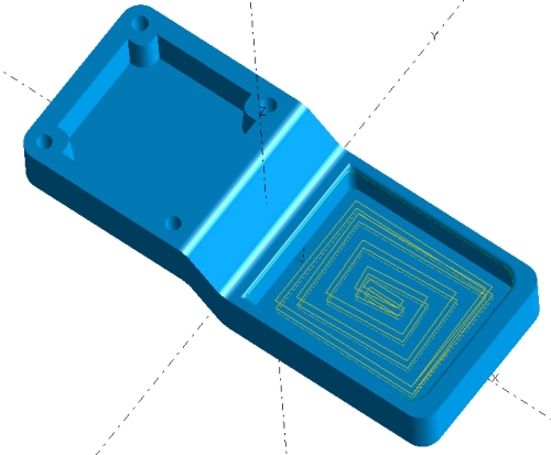
In this exercise, you will load a previously created SmartCAM process model and rough out a pocket. The image to the right shows a graphics view of the completed exercise.
In this example, some preparatory work has already been completed for you. The existing process model file contains part geometry imported from a CAD modeling system. In this model, the boundary curves have been generated, and tooling is configured.
This exercise briefly introduces SmartCAM machining concepts and illustrates how quick and easy it is to generate toolpath with SmartCAM. Do not worry if you do not understand exactly why each of the following steps is required. These questions will be cleared up in later exercises.
Concepts Explored
- Load an existing process model
- Using the Planner to select Tools and Operations
- Using Process - Rough to generate toolpath
- Verifying the generated toolpath
- Creating NC code
Step One: Load a Process Model
From the SmartCAM menu, choose File - Open.
In the Open dialog, locate and select qsmill01.pm5.
Step Two: Select the Rough Operation Step
Select the tool required to rough out the pocket in the part model. The Tool and Step are already created with appropriate feeds and speeds.
- Make sure you are in CAM (Step) mode using the Insert Properties Bar..
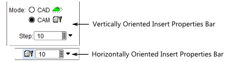
- Select 10:Rgh Mill from the input field's pop-up pick list. Click on the gray
box on the right-hand side of the Step text input field. This opens a pop-up list of available Steps.
You can also type "10" into the input field or select it from the List View. For this type of selection, the List View Context view works best.
- Click the Insert Properties Bar Tool Clearance box and set the value to .75.

Step Three: Generate Pocket Roughing Toolpath
Create the pocket roughing toolpath using the previously selected Step.
- Select Process - Rough from the menu, then select the Pocket task from the task set.
- Make sure the Container
 button is enabled on the Insert Properties Bar. This ensures that the toolpath is created in a container.
 - On the Pocket Roughing panel, make the following settings:
- Depth of Cut: .2
- Path Type: True Spiral
- Boundary: 61
You can type in the value "61" or select it from the input field's pop-up pick list (click on the gray box at the right end of the input field) or select it from the list view. If using the Context list, in the List View, scroll down and select element 61. In List View's tree-based views, expand Layer 2, then the first Wireframe Profile to find element 61.
When you select the Boundary element, the First Pass and Final Pass levels are automatically calculated based on the Boundary element's Z Level and Profile Top.
- Click Go to generate the toolpath.
When finished, the toolpath is displayed in the graphics view. There is a new element in the list view: element 77 Pocket. This is a Process Container that contains all the toolpath geometry you just created.
Step Four: Verify the Toolpath
Use Verification to verify your toolpath before generating NC code.
- Select Process - Verification or click the Verify Toolpath icon
 on your toolbar.
 - Set Speed to 4.
- Click the VCR type Play button.
During verification, you can change the playback speed by typing in a digit between 0 and 9 or use the + and - keys. If Verification runs too fast or too slow even when adjusting the speed, check out this document for instructions on adjusting the speed further. - When Verification is complete close the window.
Step Five: Generate NC Code
The format of the NC code is controlled by the selected SMF/CGT file pair. For this tutorial, you will use pre-configured files shipped with SmartCAM.
- Select Process - Code or click the Create NC Code icon
 on your toolbar.
 - Choose a path and filename to store the NC code. You can enter the path directly into the "Code File:" input field or click File Select to display a File Open dialog.
- Click Choose to open the Job Information dialog box.
- On the Machine tab, click SMF File to make it active, then click File Select.
- Pick the lsmill.smf file from the list of available files.
If you do not find this file or any SMF files, look in the directory where you extracted your Learning SmartCAM sample data or in your SmartCAM Common files directory. - Repeat using CGT File: to select the CGT file. Select lsmill.cgt.
- Accept the selections. The 'Machine=' status now shows 'LSMILL.SMF'.
- Enable Open Code File so that when the NC code file is generated it will be opened in your default code editor. This feature uses Windows File Association. If a valid text editor is not mapped to your NC code file extension, you may be prompted to establish the association.
- Click Create Code to generate the NC code.
- Click Close to close the Code panel.
The NC code file is generated and stored using the path you provided. You can open it with any text editor.
Done
This exercise is complete.