Color Display
Introduction
The Windows Theme color settings control the color of the borders, highlighting, window text, and the desktop area. To change these settings, select Appearances from the Display Properties control panel.
SmartCAM uses information in the SmartCAMcnc.INI file for other color settings, such as
default Step/Layer colors, graphic view indicators, control panel markers, and others.
There are two sections of the SmartCAMcnc.INI file that work together to provide the colors
available to SmartCAM: [ColorTable] and [ColorTableIndex].
ColorTable
There are 64 entries, numbered 0 through 63.
Click here to display the current default Color Table. The following is an example of the
[ColorTable] settings.
[ColorTable]
Color0=0 0 0
Color1=0 170 255
 . . .
Color63=140 140 140
Each line in the table defines an RGB (red, green, blue) value for a color. You can modify the 64 colors that SmartCAM uses by adjusting the values for red, green, and blue on these lines. The first number is the value for red, the second number is the value for green, and the third number is the value for blue. RGB values range from 0 (absence of the color) to 255 (full intensity of the color).
The displayed color is the result of combining the three RGB values. For example, the RGB setting 0 0 0 produces black (absence of all three RGB colors), while 255 255 255 produces white (full intensity of all three RGB colors), and 128 128 128 (the middle value for all three RGB colors) produces a neutral gray.
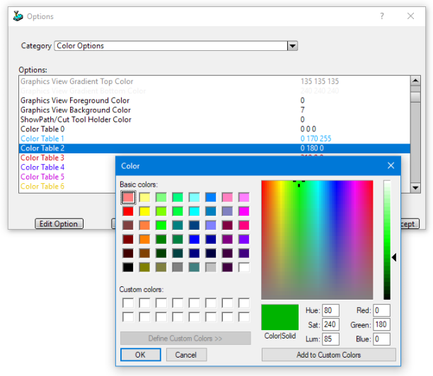
Use the "Color Options" category under Utility - Options to modify the SmartCAM color table. There are 64 individual Option selections, one for each of the Color Table entries. The RGB values for the color are shown. Additionally, the Option preference text is displayed in the same color as the provided color values.
ColorTableIndex
The [ColorTableIndex] section also contains 64 entries, numbered 0 through 63. These lines assign
a color number, from the [ColorTable] to a position in the color table index. This determines
how SmartCAM assigns the colors in the color table to steps and layers in the graphic and list views.
Click
here to display the current default ColorTableIndex. The following is an example of the
[ColorTableIndex] settings:
[ColorTableIndex]
Color0=8
Color1=1
   . . .
Color7=15
   . . .
Color63=63
In the above example, ColorTableIndex number 0 uses the color stored in Color8 of the Color Table, while Color7 uses the Color Table entry at index 15. The remaining ColorTableIndex values use a 1-to-1 mapping, for example, Color Table Index 2 points to Color Table 2.
The actual display of color on your screen is affected by the video card and monitor being used, as well as settings made in the Windows Display Control Panel applet.
To see how this works in your application, switch to CAD mode and then select Add Layer from the Insert Bar pop-up menu to open the Add Layer dialog box. You will see the 64 colors displayed in index order. If you change the color index, the display on this panel will change accordingly.
If you examine the ColorTableIndex, you will notice that the color 0 from the color table (black) is not assigned to a color table index number. This is because color 0 is assigned as the default value for the background variable. Geometry using the same color as the background color is not visible when drawn in the graphic view.
Use the "Color Options" category under Utility - Options to modify the SmartCAM Color Table Index. There are 64 individual Color Table Index selections, one for each of the ColorTableIndex properties. Select the Color Table index number for each option.
Graphical User Interface (GUI) Colors
The [Gui] section of the SmartCAMcnc.ini file uses RGB color values to set the colors
for various elements of the SmartCAM application window. You can change these colors by changing their associated
RGB values.
Items that contain an Options Preference: string can be modified from Utility - Options - Color Options. The text next to the label, Options Preference: is the property description from the Options window.
FixedFacesets the background color of the control panels. If not set in the INI file, SmartCAM will use the user's current Windows theme color.Blacksets the color of arrows, button outlines, and lines used for other borders.RequirementMsgColor
Options Preference: Requirement Message Color
Sets the text color for the Requirements area on the control panel title bars. This is the text displayed when a panel has a requirement, such as an active layer, step, tool type, or group, that you have not yet satisfied.SelectedPanelItemText
Options Preference: Active UI Item Color
Sets the color for the current active panel input's label. Setting this value to a noticeable color makes it easier to locate the currently active input on a panel.HighlightColor
Options Preference: Active Group Highlight Color
Sets the color used for selected surfaces when using OpenGL and the Shaded Surface display mode is enabled.BackfaceColor
Options Preference: Surface Back Face Color
Sets the color used for the "back" of surfaces, surfaces where the normal is inverted. This color is used when running with OpenGL and when Highlight Inverted Surfaces is enabled in Display Modes.
The following options are set in the [Defaults] section of the
SmartCAMcnc.ini file. Like the [ColorTableIndex] entries, the following keys expect a
reference to the [ColorTable].
ForegroundColor
Options Preference: Graphics View Foreground Index
Sets the color for axis lines and the cursor.BackgroundColor
Options Preference: Graphics View Background Color
Sets the color for the graphics view background. Ensure that no other color table index variables use this value, as the geometry will be assigned the same color as the graphic view background and, therefore, cannot be seen.
Related Topics
Integration with SmartCAM User Interface